User Tools
domain_models:navigation-stack:start
Table of Contents
Flexible Navigation Stack
The flexible navigation stack is a set of components that realize specific navigation services to provide a flexibly applicable navigation capability for a service robot. The services defined (service definitions) for the navigation stack are a typical example of the Composition Tier 2 contents of the RobMoSys Ecosystem. This navigation stack can be used with various robot platforms and different kinds of sensors. Moreover, it is able to deal with unstructured and dynamic environments of variable scale. The focus hereinafter is to emphasize the general design choices and architectural decisions of the navigation stack components. After that, the following section provides some technical details and references for the concrete open-source components that can be used already now, e.g. with the Robotino3 platform.
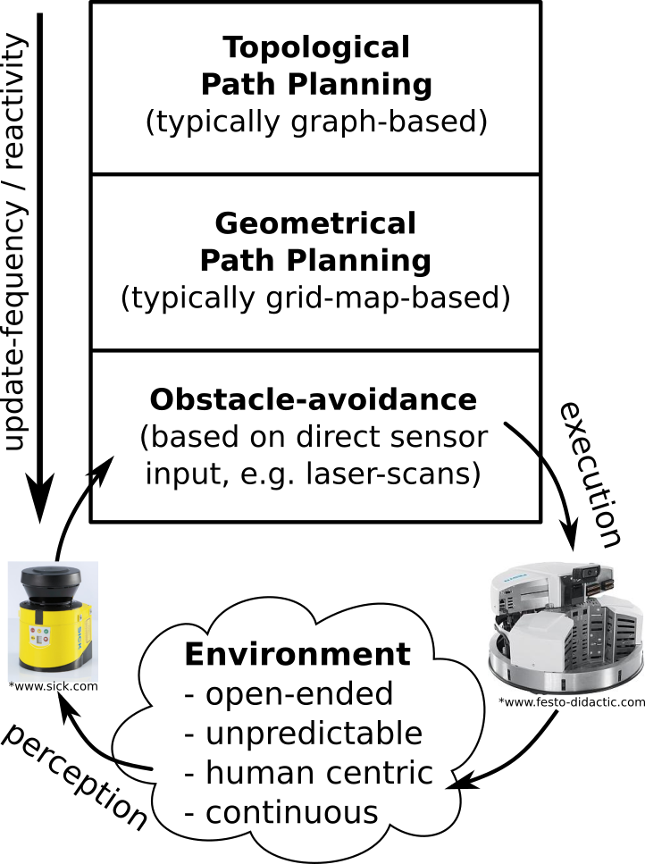
The figure on the right illustrates the three main levels of the navigation stack. These levels describe the shared responsibilities between different parts of the navigation stack. These responsibilities are assigned top down according to the subsidiarity principle (as explained next).
Obstacle Avoidance Level
The bottom level defines components (a full list is provided further below) related to the fast and reactive obstacle-avoidance navigation loop. This loop ensures that regardless of where the robot has to move next, this movement will not cause any collisions and the robot will not be commanded to execute a physically invalid movement considering the robot's kinematic and dynamic constraints. Therefore this loop will only command navigation values that never lead to a collision even if these commands might not directly lead toward the next goal (e.g. because of the need to avoid a suddenly appeared obstacle in between). Consequently, this loop might lead to a globally non-optimal, yet collision-free, navigation.
Geometrical Path Planning Level
At the middle level, a geometric path planner calculates intermediate way-points based on a grid-map of the current environment. The planner relies on this map, which is updated during the navigation to accommodate for changes in the environment. A localization component estimates the current position of the robot within that maps. Several existing path-planning algorithms (using A* for example) allow the generation of intermediate way-points to be individually approached by the lower obstacle-avoidance level. In contrast to the lower obstacle-avoidance level, this intermediate geometric path planing level has a global view on the mapped environment. This is useful to e.g. avoid local minima (by generating intermediate way-points around them). It is worth mentioning that this intermediate level typically does not generate full trajectories (to be exactly executed by the lower level), but sparse intermediate way-points. These way-points are within a direct line of sight, which allows approaching them individually by the lower level without requiring a map. Overall, this enables a clear separation of concerns between the two lower levels and avoids several disadvantages with respect to wasting resources (due to e.g. too frequent need for path re-planning) continuous velocity changes and too tight (i.e., inflexible and hardly exchangeable) coupling with the lower level.
Topological Path Planning Level
In some cases, even the intermediate level is not sufficient. For instance, if a robot needs to navigate in an entire building consisting of several floors, maybe connected over elevators, then building a single huge grid map becomes complicated, too inefficient and too resource consuming. In these cases, it is rather reasonable to calculate several smaller grid-maps (e.g. one for each level or room in the building) and to concatenate these grid-maps in a topological map (which is typically a graph). The responsibility of this top level is to provide a logical plan how to navigate through the separated maps, e.g. through levels or rooms of a building.
Flexibility in the Navigation Stack
The separation of the navigation components into these three levels has several advantages. The levels can be composed to individual navigation solutions best fitting the needs of the application or the current environment a robot is navigating in. According to these needs the size of the stack can be changed, with the bottom level being the most versatile and configurable one. For instance, some scenarios might require to manually command a robot using a joystick. In that case, both upper levels would be replaced by a simple joystick driver component, while the collision avoidance level still validates the navigation commands. In other scenarios, a robot might always navigate in a single map only. For that the geometrical path-planner on the middle level (without the topological path planner on top) is fully sufficient. Of course, there are also scenarios where all three levels are needed. Even in these latter cases, components on the individual levels can be flexibly exchanged (even at run-time, while moving) by alternatives because of a clear separation of responsibilities on each level and due to the clear interfaces between the levels. For example, it is possible to exchange free navigation with corridor-based navigation1) to make the robot move only within predefined tracks.
The navigation stack components and services
The figure below illustrates the interaction of the navigation components over generic navigation services. While the navigation services are always stable, there are several alternatives for each of the navigation components (see below) that realize the same services but internally implement different algorithms. This decoupling between a component's internal implementation and the component's service-based interaction is a fundamental principle in RobMoSys that enables a flexible reuse (i.e., exchange) of components by alternatives with unique selling points and thus makes the navigation stack flexibly usable in different applications with different requirements with respect to envisioned environments and the used robot platforms.

The navigation stack consists of two hardware-related components, namely Laser and BaseServer. These two components abstract away the used hardware. While the components themselves are specific to a particular platform (e.g. Robotino3, PAL Tiago, etc.), they implement the following services that are platform-independent:
- BaseServer
- The BaseServer acts as a hybrid component, it is both a sensor component in the sense that it provides updated odometry values, and as a actuator component in the sense that it receives navigation commands to be executed by the base platform.
- provides BaseStateService: PushPattern<DataType=CommBasicObjects.CommBaseState>: This service continuously provides the current geometric position (i.e., odomentry) of the base platform.
- provides NavigationVelocityService: SendPattern <DataType=CommBasicObjects.CommNavigationVelocity>: This service receives navigation-velocity command values which are executed by the base platform. The base platform executes the latest available navigation command until a new value arrives and overrides the previous value.
- provides LocalizationUpdateService: SendPattern < DataType = CommBasicObjects.CommBasePositionUpdate >: This is an optional service that allows correcting the robot's pose (i.e., its odometry) from a localization component (see below).
- Laser
- The Laser component receives odometry updates and publishes new laser-scans together with the latest available odometry value. This component is one classical type of a scanner component.
- requires BaseStateService (see explanation above)
- provides LaserService: PushPattern <DataType=CommBasicObjects.CommMobileLaserScan>: This service continuously provides the current laser-scan including the CommBaseState (as the geometric frame) from the time when the laser-scan has been recorded.
The other three navigation components implement the different capabilities of the navigation stack, namely (1) obstacle avoidance, (2) mapping, and (3) path-planning. Again, similar to the two hardware-related components above, the three components internally implement a specific algorithm and are exchangeable due to the following algorithm-independent service definitions that they individually implement:
- Mapper
- This component receives a current laser-scan and accumulates the information from this scan into a locally maintained grid-map.
- requires LaserService (see explanation above)
- provides CurrGridMapPushService: PushPattern <DataType=CommNavigationObjects.CommGridMap>: This is an updated grid-map.
- Planner
- This component takes a current grid-map and the current destination location2) as input and calculates a path (consisting of intermediate way-points) to reach that destination.
- requires CurrGridMapPushService (see explanation above)
- provides PlannerGoalService: PushPattern < DataType = CommNavigationObjects.CommPlannerGoal >: This is the next intermediate way-point for the platform to approach.
- ObstacleAvoidance
- This component implements an obstacle-avoidance algorithm, such as e.g. the Curvature Distance Lookup (CDL)3) approach. This components takes two inputs, namely the current laser-scan and the next way-point to approach and calculates a navigation command that approaches the next way-point on the as direct curvature as possible avoiding any collisions.
- requires LaserService (see explanation above)
- requires PlannerGoalService (see explanation above)
- requires NavigationVelocityService: provides navigation-velocity commands to be executed by the base platform, thus closing the loop back to the BaseServer (see explanation above).
- optional Localization
- This component implements a localization algorithm (such as e.g. AMCL) based on the current laser-scan to calculate a current actual position of the robot within the environment. This position is communicated through the LocalizationUpdateService (see below) to correct the robot's odomentry (i.e., to improve the accuracy).
- requires LaserService (see explanation above)
- requires LocalizationUpdateService: This service provides a pose update for the robot's odometry.
Overall, the three navigation components BaseServer, Laser and ObstacleAviodance together realize the lowest obstacle avoidance level (see above). The Mapper, the Planner and optionally the Localization components realize the middle geometric path planning level. Finally, the upper topological path planning level is realized by a symbolic planner component.
- SymbolicPlanner
- This is a generic component that is able to find solutions for a given problem domain. Internally, this component might implement a symbolic planner algorithm like metric-ff or lama.
- provides SymbolicPlan: QueryPattern<Request=CommSymbolicPlannerRequest, Answer=CommSymbolicPlannerPlan>: This query service allows querying for a solution for a given problem domain. The problem domain is transferred within the Request object and the solution is replied within the Answer object.
The symbolic planner component is not only used for geometric path planning but is a generic component that is used for all kinds of combinatoric problems. This component typically directly interacts with the Task Coordination Level.
RobMoSys Modeling Support
The following composition structures are directly related to the realization of the navigation stack:
RobMoSys Tooling Support
- The following page discusses the concrete models of this example using the SmartMDSD Toolchain: Support for the Flexible Navigation Stack
1)
Matthias Lutz, Christian Verbeek and Christian Schlegel. “Towards a Robot Fleet for Intra-Logistic Tasks: Combining Free Robot Navigation with Multi-Robot Coordination at Bottlenecks”. In Proc. of the 21th IEEE International Conference on Emerging Technologies and Factory Automation (ETFA), Berlin, September 6-9, 2016. Electronic ISBN: 978-1-5090-1314-2, DOI: 10.1109/ETFA.2016.7733602. Link
2)
The next destination is commanded from the behavior-coordination component (see Robotic Behavior Metamodel for further details).
3)
Christian Schlegel. “Fast local obstacle avoidance under kinematic and dynamic constraints for a mobile robot”. In IEEE International Conference on Intelligent Robots and Systems (IROS). Victoria, Canada, 1998. DOI: 10.1109/IROS.1998.724683.
domain_models:navigation-stack:start · Last modified: 2019/05/20 10:49
http://www.robmosys.eu/wiki/domain_models:navigation-stack:start
http://www.robmosys.eu/wiki/domain_models:navigation-stack:start
Page Tools

This project has received funding from the European Union's Horizon 2020 research and innovation programme under grant agreement No 732410.