User Tools
Table of Contents
Guaranteed Stability of Networked Control Systems
This is a contribution of the EG-IPC (Extension of Intrinsically Passive Control model and integration in the RobMoSys ecosystem“) integrated technical project (ITP) of RobMoSys.
Overview
At its core, the Energy-Guarded Intrinsically Passive Control (EG-IPC) ITP has developed a set of components that allows a user to create networked control systems that are guaranteed to be stable. The primary use case is teleoperation of robots with force feedback, but as will become apparent later, the energy-based approach can be applied to many other different situations. In fact, any setup where you want two systems in different places to act as if they were physically connected is a candidate for the EG-ITP approach.
At the core of the approach is an energy modeling and control viewpoint: all systems and controllers are analysed and controlled in terms of their energy production and consumption. By assuring that the energy exerted by the system as a whole does not exceed (a constant multiple of) the amount of energy inserted, the system can be analytically and practically stable and safe to interact with. We have made these techniques more accessible and interoperable by embedding them in the RobMoSys approach, creating meta-models and models to design and analyse energy-based control systems.
To achieve these results, we started by developing a metamodel (“design language”) of the bond-graph notation, which is a natural and versatile modeling language to describe multi-domain physical systems [1]. We import the standard interfaces defined in the bond-graph metamodel required to generate components suitable for the EG-IPC approach. Building from the formalization of the bond-graph entities, we developed a more pragmatic metamodel for describing, designing and analysing EG-IPC systems. Finally, we put these metamodels to the test by implementing their elements in the SmartMDSD Toolchain1) and building a concrete teleoperation use case with them.
This page is outlined as follows: we begin by presenting the motivation for this ITP, followed by the objectives and its role in the RobMoSys ecosystem. We continue by diving into the developed metamodels. Finally, we provide more details on the applications with a haptic teleoperation use case.
Why bother?
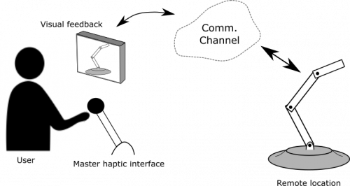
A long-standing and well known problem in teleoperation concerns the stability of haptic force-feedback systems [2]. When naïvely coupling the position commands of a master device and the force readings of a slave device, the smallest delay in the communication channel will create uncontrollable oscillations. This brings critical problems to distributed control systems like the bilateral teleoperation setup represented in Figure 1.
A common mitigation technique is the approach of passivity: when all components in a distributed system have the property of being passive - that is, that more energy cannot be extracted from a system than the one already stored or inputted into it. Thus, the system as a whole is stable. The problem with the aforementioned teleoperation setup is that undesired extra energy can be created by the quantization and delays [3], [4], leading to active behaviour that breaks passivity and hence compromising stability.
The EG-IPC ITP envisions all-time stable, loop control composable components using ‘energy guards’ to preserve passivity of the distributed system. We built upon the existing approach to guarantee passivity of components by wrapping them in a Passivity Layer (PL). Broadly speaking, this layer acts as a wrapper that monitors the energy exchange among the components inside, and limits the output when the energy balance is violated.
This energy-based approach is a somewhat novel paradigm, so it can be difficult to get started with. However, there are two main benefits that are not easily attained with other approaches:
- Energy exchange is intuitive, also for non-experts. Systems built from an energy-based viewpoint are mathematically stable, but at the same time can be reasoned about without advanced mathematics. Moreover, many other system failures or bugs can be detected using energy analysis: if a part of the system is not functional, it will typically use much more or less energy than expected. The same goes for unexpected or dangerous behaviour.
- Energy exchange is universal. Many different physical systems (mechanical, electrical, hydraulic, chemical) can be connected with (virtual) energetic bonds, as long as there is an energy-based controller available. The domain experts can create these controllers, and system integrators and architects can use a common design language to apply these components in their products.
Energy-based control in more detail
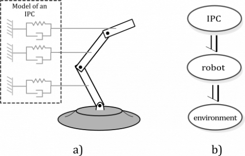
Energy-based control is a model-driven loop control strategy for multi-domain physical systems, such as robotic applications. This method relies on the exchange of energy among components to perform a specific controlled action. An energy-based controller is modeled as a dynamic system that exchanges energy with the plant [5]. This allows a robot to interact with the environment by shaping the energetic behaviour to take a desired form. Such an idea leads to formulate Intrinsically Passive Controllers (IPC), which are control components that exchange power while preserving passivity. The Figure 2 is a representation of an IPC controlling a robotic arm; the IPC is modeled as a set spring-damper elements that exchanges energy with the robot.
What is an ‘Energy-Guarded IPC’?
An Energy-Guard (EG) is an arrangement of functional blocks known as Passivity Layers (PLs) that guarantee stability of energy-based components when dealing with computational and communication delays. Figure 3 illustrates an energy-based software component (red oval) inside an arrangement of PLs (blue oval). A PL is placed on each energy-exchanging port of the ‘guarded’ component to guarantee passivity on every interaction. This arrangement is known as Energy-Guarded Component (EG-Comp). EG-IPC stands for Energy-Guarded Intrinsically Passive Controller.
Impact of EG-IPC
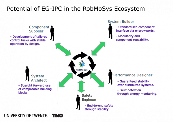
When passivity is violated, the stability of the system is not guaranteed, and often indeed violated in practice. The EG‐IPC blocks will guarantee a basic safety level due to the inherent passive structure of the block. As such, the potential user group consist of all system architects and system builders of complex robotic applications being, according to RobMoSys, the main part of the robotic applications that will be developed in the coming years. The diagram in Figure 4 illustrates the role of the EG-IPC in the RobMoSys ecosystem.
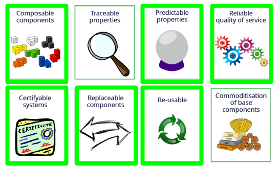
From a technical perspective, the benefits of the EG-IPC component will lead to:
- Composable components: Due to the usage of a standardized interface known as power-port, any energy-based component is guaranteed to exchange power, contributing to the composability of the system. The EG-IPC follows this architectural pattern.
- Predictable properties: The monitoring of energy provides an insight about the system behaviour. Abnormalities such as active behaviour and other faults can be predicted.
- Replaceable components: As the EG-Component architecture is composable, the ‘guarded’ component can always be replaced - i.e. by a communication channel or another controller. This benefit is only possible when the components have the standard power-ports interface.
- Re-usable: Given the composability of the EG-Component architecture, any EG-IPC component can be re-used in other applications.
Composition of the EG-IPC
Following the model-driven approach of RobMoSys, we developed metamodels to define the structure of the EG‐IPC blocks. This entails formalisation of the generic IPC structure whereby adding energy guards on the interfaces of the components where needed and additional interfaces to communicate and synchronise the energetic state.
Required metamodels
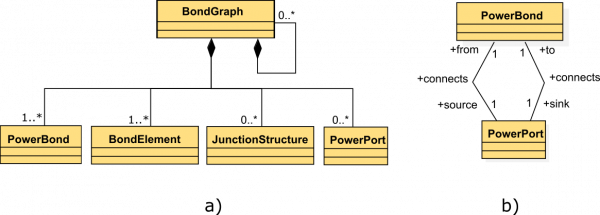
The EG-IPC project presents a formalized metamodel for the bond-graph language that captures the features of the energy-based modeling and control, which are critical to describe the power exchange between components under the energy-guarded component architecture. The bond-graph entities are represented in Figure 6. The formal definitions can be found in [6].
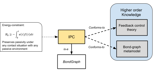
As an IPC is a controller which behaves as a physical system, its metamodel conforms to bond-graph language and feedback control as shown in Figure 7. By definition of the passivity property, an IPC has a constraint that indicates that the energy extracted from the system cannot be greater than the energy introduced to the system.
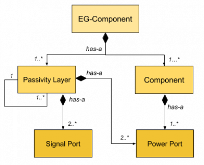
The EG-IPC metamodel, shown in Fig.8, makes use of the bond-graph and IPC metamodels to simplify the definition of its entities. The Passivity Layer component monitors the energy interacting with the system, guaranteeing the passivity and stability by bounding the extracted energy.
The generated metamodels are aligned to the RobMoSys modeling approach as they will be able to generate models suitable for:
- Human-software documentation: In form of datasheet of the (EG-)IPC components.
- Software tooling and standardization: By using the power port and power bond entities to connect components and using power as a standard interaction unit.
- (Future) verification and validation of models.
Component architecture
An EG-Component2) is any component inside a PL structure. If such component is an IPC, the EG-Component architecture will guarantee its stability when dealing with computational and communication delays. The basic operation tasks are:
- Passivity preservation
- Energy monitoring
- Fault detection
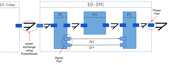
An example of an ‘EG-Component’ is shown in Figure 9. An IPC component is wrapped by two Passivity Layer. The ‘guarded’ IPC component interacts with the Passivity Layers via power ports. The example in Figure 9 follows the sign convention of the arrow representing the power bond. As described by the bond-graph metamodel, the power is exchanged in both directions of the bond.
Use Cases
Haptic Teleoperation: Manipulation Use Case
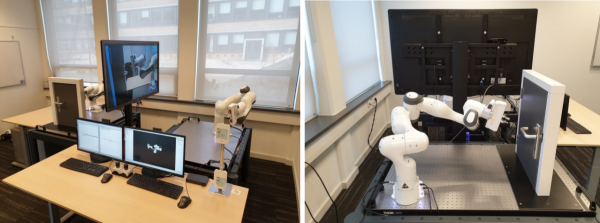
A setup was created to test the functionalities of EG-IPC in a teleoperation environment that involved the operator receiving haptic feedback over network communication. This setup is displayed in Fig 10. Similar to the example in Fig 1, it involves a Franka Emika Panda robotic arm that serves as a haptic device (right robot in left picture), a video feedback system and a remote Franka Emika Panda robot that should perform a remote task. Between the two robots, an ethernet network with a possibility to increase communication delays was installed. The main task objective of this setup was to remotely open and close a door.
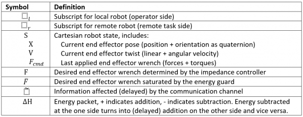
A block scheme of the teleoperation architecture that is implemented can be seen in Fig 11. The two robotic arms are connected through an impedance controller and communication channel. Surrounding these components are energy guards to ensure EG-IPC. Explanation of used symbols can be found in Table 1. The architecture is implemented using ROS. Each block indicates a ROS node, communicating the indicated variables over ROS topics. Although the adherence to the metamodel was not enforced by tooling, the implementation still conforms to the different components and their interfaces (Fig 12).
Franka Emika Panda robotic arms are used, which are controlled in real time through their control cabinets, the Franka Controller Interface (FCI). The local robot (Franka_local) is held by the operator and services as haptic device. The remote robot (Franka_remote) is the teleoperated robot that is located at the remote site. The effort interfaces are written for the Franka robots specifically. They communicate with the FCI’s in a monitored 1kHz loop. If this loop is broken, the robot will apply its safety brakes. In this loop, the effort interface writes torque commands to the actuators and receives information on the robot’s state in real time.
The impedance controller is the heart of the teleoperation controller, functioning as a virtual stiffness. It multiplies the difference between the robot poses by a tunable stiffness, which gives the desired impedance control. These control actions put in the effort to match the end effector poses of the robots.
Because passivity (and therefore stability) of the impedance controller combined with the communication channel cannot be ensured by default, energy guards surround this subset of components to guarantee stable teleoperation control. It monitors these amount of available energy in virtual energy tanks using the EG-IPC conventions. Since these components are well-defined and separated by generic interfaces, they are reusable and composable: the impedance controller is not aware what type of system it controls, and only performs calculations on positions and velocities. The passivity layer does not need specifics of the robot model to still estimate the (kinetic) energy that is spent and needed, or characteristics of the communication channel to modify its behaviour. Still, there is a role for the system architect to pick the right composition and tuning of parameters for the system to work optimally.
Integration into RobMoSys Tooling: Navigation Use Case
In order to test our adherence to the RobMoSys ecosystem, we tried to recreate our metamodels using the SmartMDSD Toolchain, which is an IDE for robotics software conformant to the RobMoSys approach. In order to make use of existing modelling and simulation components provided by RobMoSys, we worked on a use case relating to navigation: platooning of small wheeled robotic platforms like the P3Dx or the Tiago.
Platooning
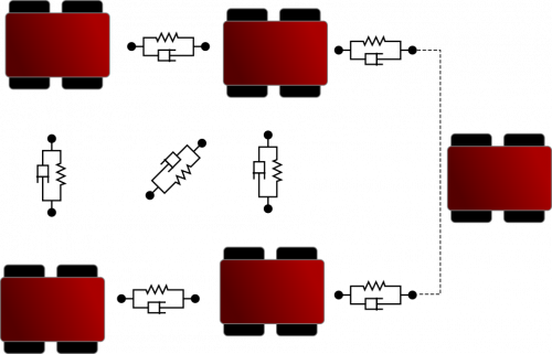
In Fig. 13 the simplest platooning use case is shown: two robots are controlled via virtual spring-dampers (impedance control).
 Fig. 13 - A simple platooning application of IPC. Robotic platforms are following each other with virtual spring-damper dynamics.
The leader robot is following a setpoint (provided by the user or a navigation algorithm). The follower follows a setpoint at a fixed distance behind the leader robot. Since it is reasonable to assume that both robots perform their control locally, and are connected by a wireless link that will not be perfect, energy guards are in place here. With the right tuning, the following will be smooth, non-oscillatory and stable. When the leader robot halts or the connection is lost, the follower robot will slow down in its approach to the latest known position. When the follower gets stuck, the leader will slow down too, while still being ‘dragged’ towards the setpoint. By monitoring the virtual forces on the setpoint, this situation can be recognized. Of course the setpoint can also be a robot that is directly remote-controlled.
In order for this to work, the only prerequisites are that the robots can be force-controlled and that the distance between two robots is known. To be force-controlled, the robot controller must be able to translate a force into an acceleration of the robot, but it is free to keep the acceleration virtual and give e.g. velocity commands. In addition, the controller must have a way to estimate the energy spent. Knowing the distance between two robots (and the rate of change of the distance) can be derived from individual positions, or from direct distance measurements.
Once this system is in place, it could be used to quickly compose a system of many such robots forming one platoon:
Implementation with the SmartMDSD Toolchain
A start was made with implementing our metamodels in the SmartMDSD Toolchain, in the form of DomainModels. Several data types and services are defined to create a software analogue of power ports. A generic power-based impedance controller was implemented, and some components for conversion of forces to rotational and linear velocities. These components were then composed into the simple leader-follower use case (Fig 15).
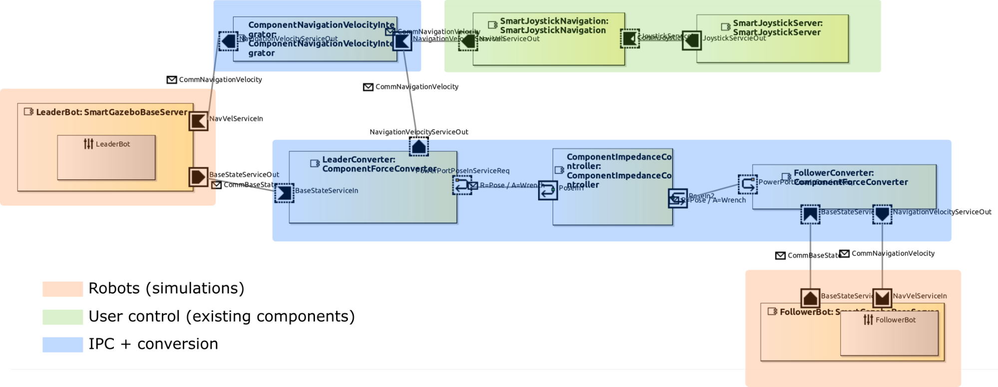 Fig. 15. Screenshot of the SmartMDSD Toolchain: system architecture of the simple leader-follower navigation use case. Existing components for robot simulation and joystick control were connected with new components for IPC.
This exercise had the following benefits:
- By being very formal about the interfaces between components, interdependencies (some unintentional) were quickly identified. For example, although for strict functionality only the position of the devices is needed, the system will function more efficiently (less filtering and processing) when also the velocity is included.
- The translation of power ports (as a modeling construct) into implementable software interfaces gave us more insight into the desired communication patterns (e.g. request-response, guaranteed delivery).
- Some of our desired modelling possibilities (wrapping (sets of) components into other components, two-way causality of ports) were not possible in the SmartMDSD Toolchain, challenging both us and the toolchain developers to be flexible.
All in all, by being formal and explicit in an implementation-focused way, many hidden problems and inconsistencies became apparent early in the process.
A note on linking to high-order (sequence) control
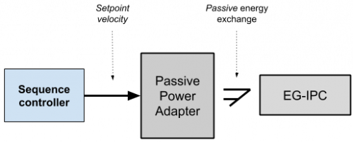
The energy-based paradigm implies the use of power as interaction currency between components [7]. This approach becomes incompatible with high-level sequence controllers when the control signal is only velocity or position. Other robotic applications, such as navigation, could be benefited by the properties of passivity if an energy consistent interface is provided. To make this interconnection, we propose using a Passive Power Adapter (PPA) to connect a generic trajectory planner to any energy-based component.
The PPA, shown in Fig.15, contains a modulated source of flow, a power estimator and a Passivity Layer. The novel PPA would provide an interface to an EG-IPC without compromising passivity as the PPA’s power port abides the estimation of power.
Bibliography
- [1] P. C. Breedveld, “Multibond graph elements in physical systems theory,” J. Frankl. Inst., vol. 319, no. 1, pp. 1–36, Jan. 1985.
- [2] P. F. Hokayem and M. W. Spong, “Bilateral teleoperation: An historical survey,” Automatica, vol. 42, no. 12, pp. 2035–2057, Dec. 2006.
- [3] J. E. (James E. Colgate, “The control of dynamically interacting systems,” Thesis, Massachusetts Institute of Technology, 1988.
- [4] R. B. Gillespie and M. R. Cutkosky, “STABLE USER-SPECIFIC HAPTIC RENDERING OF THE VIRTUAL WALL,” 1999.
- [5] R. Ortega and M. W. Spong, “Adaptive motion control of rigid robots: a tutorial,” in Proceedings of the 27th IEEE Conference on Decision and Control, 1988, pp. 1575–1584 vol.2.
- [6] R. Cobos, J. de Oliveira, D. Dresscher, and J. Broenink, “A Bond-Graph metamodel,” JOT, p. 18, 2019.
- [7] P. J. Gawthrop and G. P. Bevan, “Bond-graph modeling,” IEEE Control Syst., vol. 27, no. 2, pp. 24–45, Apr. 2007.
http://www.robmosys.eu/wiki/community:intrinsically-passive-control:start

